Been pissin’ down rain off n on, windy to boot, and enough cloud cover that my efforts to sort out what works/what doesn’t, on the armature were fraught with lots of curses at clouds and (im)patiently waiting between shade and sunlight. ‘I’m gonna have to figure something else out‘ is the final judgement. I have options, no worries there. but the ‘dumb’ version is not going to move a panel system that wieghs over 100# The motors will, but the power generation won’t: I need a pair of 100w panels if I want that to work correctly. Just not enough amperage out of the little 25w units I have on hand. At peak under optimum conditions, 25w only produces 1.5A. These are over 16 years old; likely only pushing an amp under full sunlight. Thats just not enough for motors rated at 2 amps. It might be enough to burn the brushes up,,, Not exactly my goal here.
So’sss. I’m considering adding a small system to charge a single battery, that will run the actuator, but need a way of controlling it that aint gonna cost me an arm, left buttcheek, and my right testicle. Looking in this direction,,,
But I wasn’t idle on the build.
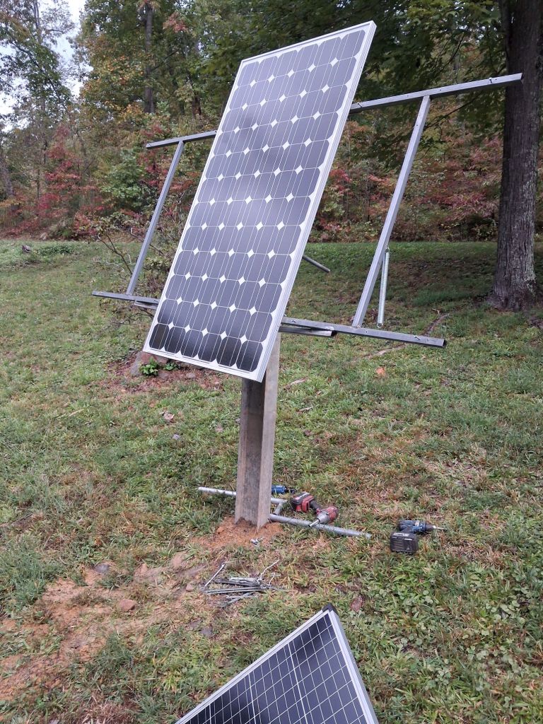
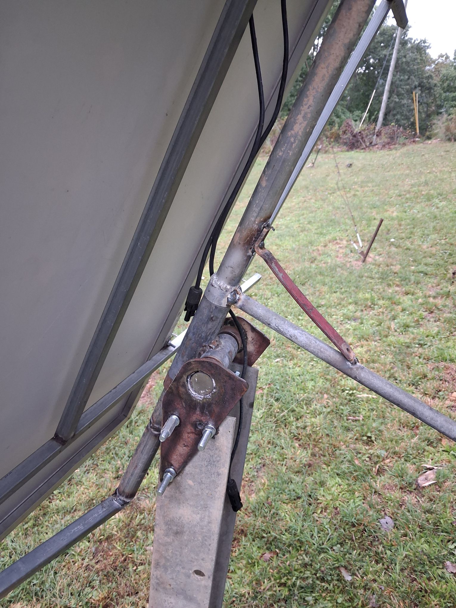
It’s hard to see, but I changed the bolts holding the U-joint to the beam. Long ones that pass through both sides of the beam; not as sloppy. Still need to put in the zerks but the whole is loosey-goosey enough that rust might actually help a bit. I wasn’t exactly rushing into 0.001″ tolerances here. Closer to 0.05″ tolerances: LOL.
I need to make the latitude adjustment arm and drill lock points on the beam for it. I’ll use an inclinometer to figure those points. I figure 45, 35, 25 will give me enough points for summer to winter shifts. Need to make a retaining system for the counter wieghts too. A simple pin and large washer will keep them on the bar. Typical cast iron dead weights are the counters.
And no, I have not put all my panels on it. That is the big boy, but not the real electron pusher. (Fact, I’ve considered getting another pair of the 12v100w units to replace it. I run them in series pairs for 24v to overcome voltage drop on my lines. That big boy already does 24v straight. (and into its own charge controller so it can do its thing.) With the cloud cover today, I wasn’t going to get much juice, so felt changing over in peices would be prudent.
—————————-
Pissy weather, frustrations in design, and regulatory hints of the future have me running on a negative charge today. Won’t go into all the deets, but I’ve been quite pissy myself today. Prolly best I live single on a little backroad that looks like an abandoned logging road. I’d probably pop rounds at some interloper coming up my hill today.
Its freeday, bills be gettin’ paid, things are mostly moving in a good direction on this project (no sign nor word from Burnout, as if I am surprised,,,) and I’m gonna take a wee break for the eve. Love y’all.
Live
Love
Laugh
Learn
LOAD!!!






Maybe use the solar panels to drive a power transistor to control a relay? Might need to put a couple of diodes in the circuit to prevent backfeeding the voltage… The trick is gonna be having the opposing voltage bleed into or off the circuit so the circuits don’t fight each other. Another thought is setting up a polarity reversing circuit. But that’s only going to work with a DC motor. Or possibly have a long spring to pull it all the way to one end of the travel so the motor only has to work one way? Possibly put a brake on it that can be disengaged with a solenoid that powers up when the system generates enough voltage differential to move?
What kind of voltages are you working with? Will scavenged automotive components work? If its too high for auto components then you might be able to use golf cart components. Or eighteen wheeler parts.
Don’t let an arbitrary box limit your design brother! You got this, you just gotta gnaw on the problem a little bit. And walk away long enough for the answer to ripen in your subconscious.
LikeLiked by 1 person
All of the motors are DC; typically 12v ratings. All require more amps than my spare panels I was planning on using put out. Or maybe I should say, that with conditions as presented with today, they were ‘lame ducks’. Except the math works out correctly The one that did ‘work’ froze when I introduced a load to the lead screw. (just grabbed the screw bare handed and squeezed. redneck brake)
All of the videos I researched today, show ‘how easy it is’, except in further thought, all of them are low voltage, low torque motors moving loads of ounces. More ‘science fair’ projects showing concept, without real world application.
The vid I introduced in this post, would work, but I need to build an amplifier circuit to drive the motor. Doable, maybe $30 in components. And I have a mess of gearing so that I can do reduction drives to increase torque out of a high RPM motor that runs on less voltage. I’m digging into old thinks because the stuff that inspired this project is lacking. And I will document it here as I progress along.
LikeLiked by 1 person